26 December 2022

note of INDUCTOR


Chapter 11 : INDUCTOR

An inductor is a passive component that is used in most power electronic circuits to store energy in the form of magnetic energy when electricity is applied to it. One of the key properties of an inductor is that it impedes or opposes any change in the amount of current flowing through it. Whenever the current across the inductor changes it either acquires charge or loses the charge in order to equalize the current passing through it. The inductor is also called a choke, reactor or just coil.

1)   Inductors don’t like change, they want to remain the same.

2)   When current increases they try to stop it with an apposing force.

3)   When current decreases they try to stop it by pushing electrons out, to try and keep it the same as it was.


gmz9455x54901z8023001.gif


Types of inductors

1)   Air-core inductor

The commonly seen inductor, with a simple winding is the air- core inductor.This has nothing but air as the core material.


2)   Iron-core

These inductors have ferromagnetic materials.

Such as iron, as the core material .The usage of such core materials helps in increase of inductance.

3)   Torodal inductors:

These inductors have a magnetic materials as the core substance to which the wire is wound .these are in circular ring shape


Working Principle of inductor :

During the Current flow through the conductor, a magnetic field is generated. These two things are linearly proportional. Therefore, if the current is increased, so the magnetic field will also increase. This magnetic field is measured in the SI unit, Tesla (T).

So, as of now, there is a magnetic field across inductors, produced by the current flowing through it.

To understand further, understanding of Faraday’s law of inductance is required. As per Faraday’s law of inductance, the generated EMF(electro motiv force) is proportional to the rate of change of the magnetic flux.

Text Box: VL = N (dΦ / dt)

Where N is the number of turns and Φ is the amount of flux.


What is self-induction?

The situation in which an EMF(Electro Motiv Force) is increase in a coil due to the change of current through the coil itself is known as self- induction.

What is mutual induction?

The situation in which a change of current in one coil increases an EMF(electro motiv force) in another neighbouring coil is called mutual induction

Permeability :


Permeability is   the   measure   of magnetization that   a   material obtains in response to an applied magnetic field.

Simply, ability   of material or electrons to become magnetized, when placed in magnetic field is called permeability


High Permeability = High Conductivity Low Permeability = Low Conductivity


Permeability depends upon

1)   Strength of magnetic field

2)   Temperature

3)   Humidity


It is denoted by μ (muon).

note of capacitor in circuit


Unit 10 : Capacitor in circuit


Capacitors (originally called electrical condensers) are analog electrical components that can collect and store electrical energy not electrical charge.

Capacitor can store energy quickly and can release energy quickly.

As a direct current flows into a capacitor, it charges with energy and releases an alternating current flow back into the circuit.Most capacitors have a positive and negative terminal.

Working principle of capacitor:

let us consider a parallel plate capacitor with a dielectric between them as shown in the below circuit. Now, apply the voltage V as shown in the circuit, plate 1 has the positive charge and plate 2 has negative charge. Across the capacitor an electric field appears. When these plates are applied with the voltage they will carry positive charge from the battery at plate 1 and negative charge on plate 2. For some time the voltage is applied and within that time the capacitor gets charged to the maximum limit of holding charge and this time is called as charging time of the capacitor.


After some time when the capacitor has reached its maximum limit of charging then we will cut the supply of power to the capacitor. For a certain time, the two plates hold a negative and positive charge. Thus, the capacitor acts as a source or electric charge


Capacitor in Series:


Series capacitors are more effective on distribution circuits with higher X/R ratio and for load variations involving a higher reactive content.

Capacitors connected in series. The magnitude of the charge on each plate is Q, C is capacitor and V is Voltage.


Series connections produce a total capacitance that is less than that of any of the individual capacitors. It is a general feature of series connections of capacitors that the total capacitance is less than any of the individual capacitances.


We can find an expression for the total capacitance by considering the voltage across the individual capacitors shown in Figure.


Q= CV …. (Chage from capacitor C and Voltage V )


Solving C= Q

V


for V gives v =


Q

. The voltages across the individual capacitors are


The total voltage is the sum of the individual voltages:


V=V1+V2+V3


Now, calling the total capacitance CS for series capacitance, consider that


V=Q =V1+V2+V3

C


Entering the expressions for V1, V2, and V3, we get


Q= Q  +  Q   + Q

C      C1          C2       C3

Canceling the Qs, we obtain the equation for the total capacitance in series C to be


1= 1  +   1   + 1

C      C1          C2        C3


Total Capacitance in Series, Cs


Total capacitance in series: 1= 1 +  1     + 1

C      C1          C2         C3


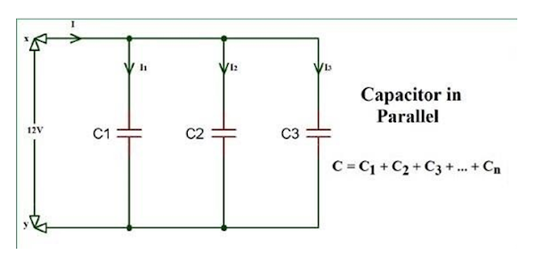
Capacitors in Parallel


Capacitors in parallel refer to the capacitors that are connected together in parallel when the connection of both of its terminals takes place to each terminal of another capacitor.

When capacitors are connected together in parallel the total or equivalent capacitance, CT  in the circuit is equal to the sum of all the individual capacitors added together. This is because the top plate of capacitor, C1  is connected to the top plate of C2  which is connected to the top plate of C3  and so on.


Using the relationship Q=CV, we see that the total charge is Q=CV

and the individual charges are Q1=C1V, Q2=C2V, and Q3=C3V. Entering these into the previous equation gives


CV = C1 V + C2 V + C3V


Canceling V from the equation, we obtain the equation for the total capacitance in parallel


C = C1 + C2 + C3


Text Box: Total Capacitance in Parallel
Total capacitance in parallel C=C1+C2+C3+⋯…..


Prepared by :Mausham aryal

FEATURED POST

DBMS NOTES

Note part 1 Note Part 2  

Most viewed