
09 January 2023
02 January 2023

27 December 2022
Notes of electro technology
COUNCIL
FOR TECHNICAL EDUCATION AND VOCATIONAL TRANING (CTEVT)
SHREE GYANODAYA SECONDARY
SCHOOL, GULMI
EXAM TYPE :INTERNAL FULL MARK :50
PASS MARK :20
SUBJECT : Electro Technology TIME :1 HOUR
तलको मध्य कुनै २ प्रश्नको उत्तर
दिनुहोस २*१० = २०
1)
PPE भनेको के हो ? यसको
प्रयोग बारेमा व्याख्या गर्नुहोस
2)
Logic Gates हरुको प्रयोग किन गरिन्छ ? AND GATE र OR GATE को Truth Table र Logical Expression
लेख्नुहोस
3)
Hazard भनेको के बुझ्नुहुन्छ ? Hazard का
प्रकारहरुको छोटो व्याख्या गर्नुहोस ।
तलका मध्ये कुनै ५ प्रश्नको छोटो उत्तर दिनुहोस ५ *६ = ३०
१)
Voltage र Current के फरक छ होला ?
२)
Capacitor
को परिचय दिदै यसको प्रयोगको बारेमा लेख्नुहोस
३)
Alternating
current(AC) र Direct current(DC) को बारेमा लेख्नुहोस ।
४)
Transistor भनेको के हो ? यसको प्रकारहरु लेख्नुहोस ।
५)
Semiconductor को प्रयोग किन हुन्छ ? Diode र Zener Diode बीच
मा फरक लेख्नुहोस ।
६) Multi-Meter को प्रयोग बाट के
के कुराको मापन गर्न सकिन्छ ? लेख्नुहोस
७) Convert गर्नुहोस
(1001001100)2 →
( ? )10
Unit 10 : Capacitor in circuit
Capacitors (originally called electrical condensers) are analog electrical components that can collect and store electrical energy not electrical charge.
Capacitor can store energy quickly and can release energy quickly.
As a direct current flows into a capacitor, it charges with energy and releases an alternating current flow back into the circuit.Most capacitors have a positive and negative terminal.
Working principle of capacitor:
let us consider a parallel plate capacitor with a dielectric between them as shown in the below circuit. Now, apply the voltage V as shown in the circuit, plate 1 has the positive charge and plate 2 has negative charge. Across the capacitor an electric field appears. When these plates are applied with the voltage they will carry positive charge from the battery at plate 1 and negative charge on plate 2. For some time the voltage is applied and within that time the capacitor gets charged to the maximum limit of holding charge and this time is called as charging time of the capacitor.

After some time when the capacitor has reached its maximum limit of charging then we will cut the supply of power to the capacitor. For a certain time, the two plates hold a negative and positive charge. Thus, the capacitor acts as a source or electric charge
Capacitor in Series:
Series capacitors are more effective on distribution circuits with higher X/R ratio and for load variations involving a higher reactive content.
Capacitors connected in series. The magnitude of the charge on each plate is Q, C is capacitor and V is Voltage.
Series connections produce a total capacitance that is less than that of any of the individual capacitors. It is a general feature of series connections of capacitors that the total capacitance is less than any of the individual capacitances.

We can find an expression for the total capacitance by considering the voltage across the individual capacitors shown in Figure.
Q= CV …. (Chage from capacitor C and Voltage V )
V

Now, calling the total capacitance CS for series capacitance, consider that
C
Entering the expressions for V1, V2, and V3, we get
![]()
![]()
![]()
![]() Q= Q + Q + Q
Q= Q + Q + Q
![]() C C1 C2 C3
C C1 C2 C3
Canceling the Qs, we obtain the equation for the total capacitance in series C to be
C C1 C2 C3
Total Capacitance in Series, Cs
![]()
![]()
![]()
![]() Total capacitance in series: 1= 1 + 1 + 1
Total capacitance in series: 1= 1 + 1 + 1
C C1 C2 C3
Capacitors in Parallel
Capacitors in parallel refer to the capacitors that are connected together in parallel when the connection of both of its terminals takes place to each terminal of another capacitor.
When capacitors are connected together in parallel the total or equivalent capacitance, CT in the circuit is equal to the sum of all the individual capacitors added together. This is because the top plate of capacitor, C1 is connected to the top plate of C2 which is connected to the top plate of C3 and so on.

Using the relationship Q=CV, we see that the total charge is Q=CV
and the individual charges are Q1=C1V, Q2=C2V, and Q3=C3V. Entering these into the previous equation gives
CV = C1 V + C2 V + C3V
Canceling V from the equation, we obtain the equation for the total capacitance in parallel
C = C1 + C2 + C3
 |
Prepared by :Mausham aryal
Chapter 11 : INDUCTOR
An inductor is a passive component that is used in most power electronic circuits to store energy in the form of magnetic energy when electricity is applied to it. One of the key properties of an inductor is that it impedes or opposes any change in the amount of current flowing through it. Whenever the current across the inductor changes it either acquires charge or loses the charge in order to equalize the current passing through it. The inductor is also called a choke, reactor or just coil.
1) Inductors don’t like change, they want to remain the same.
2) When current increases they try to stop it with an apposing force.
3) When current decreases they try to stop it by pushing electrons out, to try and keep it the same as it was.
 |
Types of inductors
1) Air-core inductor
The commonly seen inductor, with a simple winding is the air- core inductor.This has nothing but air as the core material.
2) Iron-core
These inductors have ferromagnetic materials.
Such as iron, as the core material .The usage of such core materials helps in increase of inductance.
3) Torodal inductors:
These inductors have a magnetic materials as the core substance to which the wire is wound .these are in circular ring shape

Working Principle of inductor :
During the Current flow through the conductor, a magnetic field is generated. These two things are linearly proportional. Therefore, if the current is increased, so the magnetic field will also increase. This magnetic field is measured in the SI unit, Tesla (T).
So, as of now, there is a magnetic field across inductors, produced by the current flowing through it.
To understand further, understanding of Faraday’s law of inductance is required. As per Faraday’s law of inductance, the generated EMF(electro motiv force) is proportional to the rate of change of the magnetic flux.
 |
Where N is the number of turns and Φ is the amount of flux.
The situation in which an EMF(Electro Motiv Force) is increase in a coil due to the change of current through the coil itself is known as self- induction.
The situation in which a change of current in one coil increases an EMF(electro motiv force) in another neighbouring coil is called mutual induction
Permeability :
Permeability is the measure of magnetization that a material obtains in response to an applied magnetic field.
Simply, ability of material or electrons to become magnetized, when placed in magnetic field is called permeability
High Permeability = High Conductivity Low Permeability = Low Conductivity
Permeability depends upon
1) Strength of magnetic field
2) Temperature
3) Humidity
It is denoted by μ (muon).
Chapter 12 : Transformer
Dear, CTEVT STUDENTS….
IF WE WANT TO TRAVEL THE CURRENT FOR LONG DISTANCE , THEN WE HAVE TO USE TRANSFORMERS BETWEEN SOURCE OF ELECTRICITY(SUCH A KALIGANDAKI HYDROPOWER) AND DESTINATION OF ELECTRICITY(SUCH AS FAN, BULB OF YOUR HOME)

A transformer is a device that transfers electric energy from one alternating-current circuit to one or more other circuits, either increasing (stepping up) or reducing (stepping down) the voltage.
THE TRANSFORMERS ARE USED TO INCRESE OR DECRESE THE ELECTRIC VOLTAGE
In brief, a transformer is a device that
1. transfers electric power from one circuit to another
2. does so without changing the frequency
3. It does this using electromagnetic induction and
4. when the two electric circuits are mutually inductively influenced
Working principle of transformer:

- If the primary coil have less turn and secondary coil
have more turn, the voltage will increase.
- If the primary coil have more turn and secondary coil have less turn, the voltage will decrease.
- The laminated core is the metal which is used to attract the magnetic field
Electricity is one of the biggest discoveries in human history, reshaping the planet dramatically. Today, we enjoy a variety of advantages brought about by harnessing this basic force of nature and transporting it to remote places. Faraday and Henry advanced electrical study in 1830 by connecting it to magnetism, which led to the discovery of electromagnetic induction. This discovery changed the world by paving the way for the development of alternating current generators.
The working principle of transformer is based on Faraday’s Law of Mutual Induction or Electromagnetic Induction, which happens between two circuits connected by a mutual magnetic flux. Let’s first investigate the mechanism of electromagnetic induction before moving on to the operation of transformer
TYPES OF TRANSFORMER
1. Step Down Transformer:
A Step-down Transformer is a transformer that converts a high voltage at the primary windings to a low voltage at the secondary windings. In terms of the coil windings, a step- down transformer’s primary winding has more turns than the secondary winding.
2. Step Up Transformer:
A step-up transformer is a transformer that increases the voltage from the primary coil to the secondary coil while managing the same power at the rated frequency in both coils. It converts low voltage & high current from the primary side to the high voltage & low current on the secondary side of the transformer.
3. Isolation Transformer:
An isolation transformer is a transformer used to transfer electrical power from a source of alternating current power to some equipment or device while isolating the powered device from the power source, usually for safety reasons or to reduce transients and harmonics.
4 .Air-core transformers
Air-core transformers are designed to transfer radio-frequency currents—i.e., the currents used for radio transmission; they consist of two or more coils wound around a solid insulating substance or on an insulating coil form. Iron-core transformers serve analogous functions in the audio-frequency range.
Note prepared by : Mausham aryal
CHAPTER -13 :APPLY THE PRINCIPAL OF SEMICONDUTOR
A substance that can conduct electricity is called
the conductor and a substance that cannot conduct electricity is known as the insulator. Semiconductors have properties that sit between the conductor and insulator. A diode, integrated circuit (IC) and transistor are all made from semiconductors.
Computer chips, both for CPU and memory, are composed of semiconductor materials
A semiconductor is a substance that has specific electrical properties that enable it to serve as a foundation for computers and other electronic devices. It is typically a solid chemical element or compound that conducts electricity under certain conditions but not others. This makes it an ideal medium to control electrical current and everyday electrical appliances.
Uses of Semiconductors in Everyday life
· Temperature sensors are made with semiconductor devices.
· They are used in 3D printing machines
· Used in microchips and self-driving cars
· Used in calculators, solar plates, computers and other electronic devices.

TYPES OF SEMICONDUCTOR
1) Intrinsic semiconductor:
An intrinsic type of semiconductor material is made to be very pure chemically. It is made up of only a single type of element.
Germanium (Ge) and Silicon (Si) are the most common type of intrinsic semiconductor elements. They have four valence electrons (tetravalent). They are bound to the atom by covalent bond at absolute zero temperature.
When the temperature rises, due to collisions, few electrons are unbounded and become free to move through the lattice, thus creating an absence in its original position (hole). These free electrons and holes contribute to the conduction of electricity in the semiconductor. The negative and positive charge carriers are equal in number.
The conductivity of semiconductors can be greatly improved by introducing a small number of suitable replacement atoms called IMPURITIES. The process of adding impurity atoms to the pure semiconductor is called DOPING. Usually, only 1 atom in 107 is replaced by a dopant atom in the doped semiconductor.
An extrinsic semiconductor can be further classified into:
· N-type Semiconductor
· P-type Semiconductor
N-Type Semiconductor
· Mainly due to electrons
· Entirely neutral
· I = Ih and nh >> ne
· Majority – Electrons and Minority – Holes
When a pure semiconductor (Silicon or Germanium) is doped by pentavalent impurity (P, As, Sb, Bi) then, four electrons out of five valence electrons bonds with the four electrons of Ge or Si.
The fifth electron of the dopant is set free. Thus, the impurity atom donates a free electron for conduction in the lattice and is called “Donar“.
Since the number of free electron increases by the addition of an impurity, the negative charge carriers increase. Hence, it is called n-type semiconductor.
P-Type Semiconductor
· Mainly due to holes
· Entirely neutral
· I = Ih and nh >> ne
· Majority – Holes and Minority – Electrons
When a pure semiconductor is doped with a trivalent impurity (B, Al, In, Ga ) then, the three valence electrons of the impurity bonds with three of the four valence electrons of the semiconductor.
This leaves an absence of electron (hole) in the impurity. These impurity atoms which are ready to accept bonded electrons are called “Acceptors“.
With the increase in the number of impurities, holes (the positive charge carriers) are increased. Hence, it is called p-type semiconductor.
DIODE SEMICONDUTOR
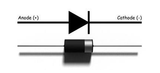
A diode is a two-terminal electronic component that conducts current primarily in one direction (asymmetric conductance); it has low (ideally zero) resistance in one direction, and high (ideally infinite) resistance in the other.
The diode have two points, one anode and anathoer cathode.
DIODE ARE ONE DIRECTIONAL(Positive to Negative ).
Diode are used in turning AC to DC , Inverters, Powe r supply etc
Working principle of semiconductor diode
N-type have a significant number of free electrons and very few holes. But in P-type, It has a high concentration of holes and very few free electrons. For this reason, the free electron from n side will diffuse into the p side and recombine with holes present there, leaving position is not movable ions in n side and creating negative immobile ions in the p-type side of the diode.
Hence, revealed positive giver particles present in the n-type side close to the junction edge. Correspondingly, revealed negative acceptor particles present in the p-type side close to the junction edge.
For this reason, the number of positive ions and negative ions will accumulate on n-side and p side too. This region is formed in the depletion region due to the free carrier in the region.

Because of the nearness of these positive and negative ions, a static electric field called as barrier potential is made over the PN junction of the diode. It is classified “barrier potential” since it goes about as an obstruction and opposes the further migration of gaps and free electrons over the junction.
.
TYPES OF DIODES
Light Emitting Diode (LED)
When an electric current between the electrodes passes through this diode, light is produced. In other words, light is generated when a sufficient amount of forwarding current passes through it. In many diodes, this light generated is not visible as there are frequency levels that do not allow visibility. LEDs are available in different colours. There are tricolour LEDs that can emit three colours at a time. Light colour depends on the energy gap of the semiconductor used.
Laser Diode
It is a different type of diode as it produces coherent light. It is highly used in CD drives, DVDs and laser devices. These are costly when compared to LEDs and are cheaper when compared to other laser generators. Limited life is the only drawback of these diodes.
Avalanche Diode
This diode belongs to a reverse bias type and operates using the avalanche effect. When voltage drop is constant and is independent of current,
the breakdown of avalanche takes place. They exhibit high levels of sensitivity and hence are used for photo detection.
Zener Diode
It is the most useful type of diode as it can provide a stable reference voltage. These are operated in reverse bias and break down on the arrival of a certain voltage. If current passing through the resistor is limited, a stable voltage is generated. Zener diodes are widely used in power supplies to provide a reference voltage.
Zener diodes are used for voltage regulation, as reference elements, surge suppressors, and in switching applications and clipper circuits
Prepared By :Mausham Aryal (GSS 2079)
CHAPTER 14 : FAMILARIZE WITH TRANSISTOR
A transistor is a semiconductor device used to amplify or switch electrical signals and power. The transistor is one of the basic building blocks of modern electronics.
Transistors are also used for low-frequency, high-power applications, such as power-supply inverters that convert alternating current into direct current. Additionally, transistors are used in high-frequency applications, such as the oscillator circuits used to generate radio signals.

A transistor can act as a switch or gate for electronic signals, opening and closing an electronic gate many times per second. It ensures the circuit is on if the current is flowing and switched off if it isn't. Transistors are used in complex switching circuits that comprise all modern telecommunications systems. Circuits also offer very high switching speeds, such as hundreds of gigahertz or more than 100 billion on-and-off cycles per second.
Transistors can be combined to form a logic gate, which compares multiple input currents to provide a different output.
Computers with logic gates can make simple decisions using Boolean algebra. These techniques are the foundation of modern-day computing and computer programs.
TYPES OF TRANSISTOR
1) NPN Transistor (Negative Positive Negative Transistor.):
NPN is one of the two types of Bipolar Junction Transistors (BJT). The NPN transistor consists of two n-type semiconductor materials and they are separated by a thin layer of p-type semiconductor. Here, the majority charge carriers are electrons while holes are the minority charge carriers. The flow of electrons from emitter to collector is controlled by the current flow in the base terminal.
A small amount of current at base terminal causes a large amount current to flow from emitter to collector. Nowadays, the more commonly used bipolar transistor is NPN transistor, because the mobility of electrons is greater than mo
2) PNP Transistor(Positive Negative Positive Transistor.)
The PNP is another type of Bipolar Junction Transistors (BJT). The PNP transistors contain two p-type semiconductor materials and are separated by a thin layer of n-type semiconductor. The majority charge carriers in the PNP transistors are holes while electrons are minority charge carriers. The arrow in the emitter terminal of transistor indicates the flow of conventional current. In PNP transistor, the current flows from Emitter to Collector.
Chapter 15 : Familarize with IC
integrated circuit (IC), also called microelectronic circuit, microchip, or chip, an assembly
of electronic components, fabricated as a single unit, in which active devices (e.g., transistors and diodes) and passive devices (e.g., capacitors and resistors) and their interconnections are built up.
An IC can function as an amplifier, oscillator, timer, counter, logic gate, computer memory, microcontroller or microprocessor. An IC is the fundamental building block of all modern electronic devices

There are two main types of integrated circuits: Digital ICs or
Analog ICs.
In this type of ICs, the input and output both signals are continuous. The output signal level depends upon the input signal level and the output signal level is a linear function of input signal level. Linear ICs or analog ICs are most commonly used as audio frequency amplifier and radio frequency amplifier. Op amps, voltage regulators, comparators and timers are also well-known examples of linear ICs or analog ICs.
The logic Gates, such as AND gate, OR gate, NAND gate, XOR gate, flip flops, counters; microprocessors are some well-known examples of digital ICs.
These ICs operate with binary data such as either 0 or 1. Normally in digital circuit, 0 indicates 0 V and one indicate +5 V. Digital ICs are commonly used in many electronics projects, and are often used in Ardino .
Prepared By :Mausham Aryal(GSS 2079)
Subscribe to:
Posts (Atom)
Most viewed
-
 model questions Long question 2*10 1)What is computer graphics ? Explain the different image types used...
 -
 Important questions of DBMS LONG QUESTION १.Data modeling भनेको के हो ? यसको प्रकारको बयान गर्नुहोस् । २. Normalization भने...
 -
What is PHP? PHP ( Hypertext Preprocessor ) is a widely-used open source general-purpose scripting language that is especially suited for ...